Bridge engineering · Expert session
Cable Vibration in Cable-Supported Bridges: Causes and Control
Rain-wind vibration, vortex shedding, galloping and deck excitation of stay cables: how each is checked, how dampers and cable surfaces control them, and how cable force and damping are measured on site.
As cable-supported bridges get longer and lighter, they get livelier. Main spans of cable-stayed bridges have grown from a few hundred metres in the 1960s to more than 1,100 m, and stay cables of 500 m or more are now built. These long cables are light, flexible and have almost no damping of their own, and they are the parts of a modern bridge that most often vibrate in the wind. This expert session explains why bridges and their cables vibrate, how each kind of vibration is checked, how damping is added and the cable surface shaped to stop it, and how cable forces and damping are measured on site.
The dynamic problems of a cable-supported bridge
Bridge aerodynamics as a discipline began with the collapse of the Tacoma Narrows Bridge in 1940, when its slender 853 m suspension span failed by torsional flutter in a wind of about 19 m/s. Since then the problems have been sorted into two groups.
- The whole structure: flutter of the deck (an aerodynamic instability that must be kept well above the design wind speed), vortex-induced vibration of the deck or towers at moderate winds, and buffeting by turbulence, which adds to the design forces. These are checked by section model and full aeroelastic wind tunnel tests and set the deck shape; see the wind load tool for the static part. Serviceability under traffic and pedestrians is a separate check of measured frequencies and accelerations against comfort curves such as the Reiher and Meister curves.
- The cables: stays, hangers and even main cables vibrate on their own or are driven by the deck and towers. Uncontrolled cable vibration shortens the fatigue life of the wires, damages anchorages, guide pipes and dampers, and alarms the public long before anything is at risk.
The rest of this page is about the cables, because on a modern cable-stayed bridge that is where most vibration problems are found and solved.
Why stay cables vibrate so easily
A stay cable is a long, taut string. Its natural frequencies are close to those of a taut string:
with T the cable force, m the mass per metre and L the length. A 400 m stay has a fundamental frequency of only about 0.3 Hz and dozens of modes below 10 Hz, so there is almost always a mode that matches the frequency of some wind effect. And there is very little to stop it: the inherent damping of a stay cable is tiny.
| Cable type | Inherent damping ξ (% of critical) |
|---|---|
| Grouted stay in a PE duct | 0.08 to 0.13 |
| Locked coil rope | 0.15 to 0.30 |
| Galvanised strands in an HDPE duct filled with wax | 0.10 to 0.18 |
| Individually protected strands in an HDPE duct | 0.12 to 0.20, falling with length (about 0.24 − 0.0006 L, with L in metres) |
Longer cables have less damping, and the damping measured on real long stays is often lower still. In the design case study later on this page, the inherent damping of the stays was 0.03% to 0.20%.
The five ways a cable vibrates
Rain-wind vibration
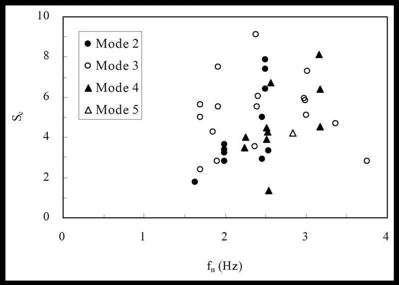
The most common and most damaging cable vibration. In light to moderate rain and wind, water forms rivulets on the upper and lower surface of an inclined cable. The upper rivulet changes the shape of the cross-section the wind sees and oscillates with the cable, and the cable can then vibrate violently. Rain-wind vibration was first identified on the Meiko West Bridge in Japan in the 1980s and has since been seen on many bridges, the Fred Hartman Bridge in Texas among them.
- wind of about 8 to 15 m/s (observations range from 5 to 20 m/s), with the cable inclined away from the wind at a yaw angle of about 20° to 60°;
- frequencies of about 1 to 3 Hz, mostly in the second or third mode;
- amplitudes that can reach a metre or more, mostly in the plane of the cable;
- smooth HDPE surfaces, on which water rivulets form and move easily.
The usual design criterion is a minimum Scruton number, a measure of the mass and damping of the cable compared with the air it displaces:
This is the PTI recommendation. Research suggests that a cable with an effective aerodynamic surface may need only about half this value, but that has to be shown for the actual surface. Note that some documents define the Scruton number with the logarithmic decrement δ instead of ξ (Sc = 2mδ / ρD²), which gives numbers about 4π times larger, so always check the definition before comparing values.
Vortex shedding
Vortices shed alternately from the two sides of the cable at a frequency f = St·U/D, with a Strouhal number St of about 0.2 for a circular cable. When that frequency matches a cable mode, the cable locks in and vibrates. The amplitude is small, a few millimetres, because the effect limits itself, but it happens in high modes at low wind speeds and lasts long, so it is a fatigue concern rather than a strength one. The amplitude falls in proportion to the Scruton number, and modest damping usually controls it.
Dry galloping
A dry inclined cable in a skew wind can become unstable at high wind speed, vibrating in its lowest mode with amplitudes of metres. Iced cables gallop for the same reason: ice makes the section asymmetric. PTI gives an onset wind speed of
The formula is very conservative, and dry galloping of real stays is still being researched. In wind tunnel work at the Technical University of Denmark it occurred only on the plain cable model, not on cables with helical fillets or a pattern-indented surface.
Wake galloping
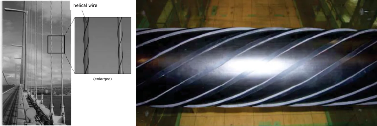
A cable standing in the wake of another, typically within a few diameters to about ten diameters, can be driven into an elliptical orbit by the vortices shed from the upstream cable. Parallel twin stays and the paired hangers of suspension bridges are prone to it: the hangers of the Akashi Kaikyo Bridge showed wake-induced vibration after completion and were fitted with helical wires. Because the mechanism is still not fully understood, the best design approach is to avoid close spacings in line with the dominant wind.
Deck and tower excitation
Wind and traffic move the deck and towers, and with them the cable anchorages. Two cases matter:
- Direct resonance, when a deck or tower frequency is close to a cable frequency and the anchorage moves across the cable.
- Parametric excitation, when the anchorage moves along the cable at about twice a cable frequency, so the cable force varies and pumps energy into the cable, mostly in its lowest mode.
The check compares each cable's frequencies with the deck and tower modes, n = α · f_deck / f_cable with α = 1 for resonance and 0.5 for parametric excitation, flagging any n close to a whole number within a margin of about 5%. Where resonance is possible, the cable amplitude under the anchorage motion from a buffeting analysis is computed and compared with the limits.
Amplitude limits
The French CIP recommendations give two limits that are widely used:
- for appearance and the public, the amplitude v at midspan should stay below L/1600 (v/L < 0.0006) in winds up to about 15 m/s;
- for the anchorage, the cable rotation at the anchorage, about πv/L, should stay below the allowable angle of the anchorage, generally 0.5° to 0.6°.
Damping: where it comes from
The damping available to a cable is the sum of several sources, and the designer chooses which ones to rely on:
| Source | Typical size | Comment |
|---|---|---|
| Inherent (material and friction) | 0.03% to 0.3% | falls with cable length |
| Aerodynamic | ξ_aero = ρ D C_D V / (4 ω m) | grows with wind speed; larger for out-of-plane motion, so cables mostly vibrate in plane |
| Deviators and guide pipe bushings | up to about 0.3% | depends on detailing |
| Dampers | up to about 0.5 a/L per damper | a = distance of the damper from the anchorage |
| Cross ties | some damping, mainly higher frequencies | see below |
Dampers and the a/L rule
A damper fixed between the cable and the deck at a distance a from the anchorage adds damping only through the small movement of the cable at that point. For a viscous damper on a taut cable, the added damping follows a universal curve:
Three consequences shape every damper design:
- There is a ceiling. The best a damper can do in any mode is about 0.5·a/L. A damper 2 m up a 100 m cable can give up to 1%; the same damper on a 400 m cable gives at most 0.25%.
- The damper is tuned to a mode. The optimum damper constant is c_opt ≈ √(T m) / (π n a/L), so a damper tuned for the second or third mode (rain-wind) gives less in the others.
- Stiffness costs damping. Any stiffness in the damper or its support lowers the curve, so dampers with little stiffness suit cables, which already have their own restoring force. Friction and high-damping rubber dampers also depend on the amplitude.
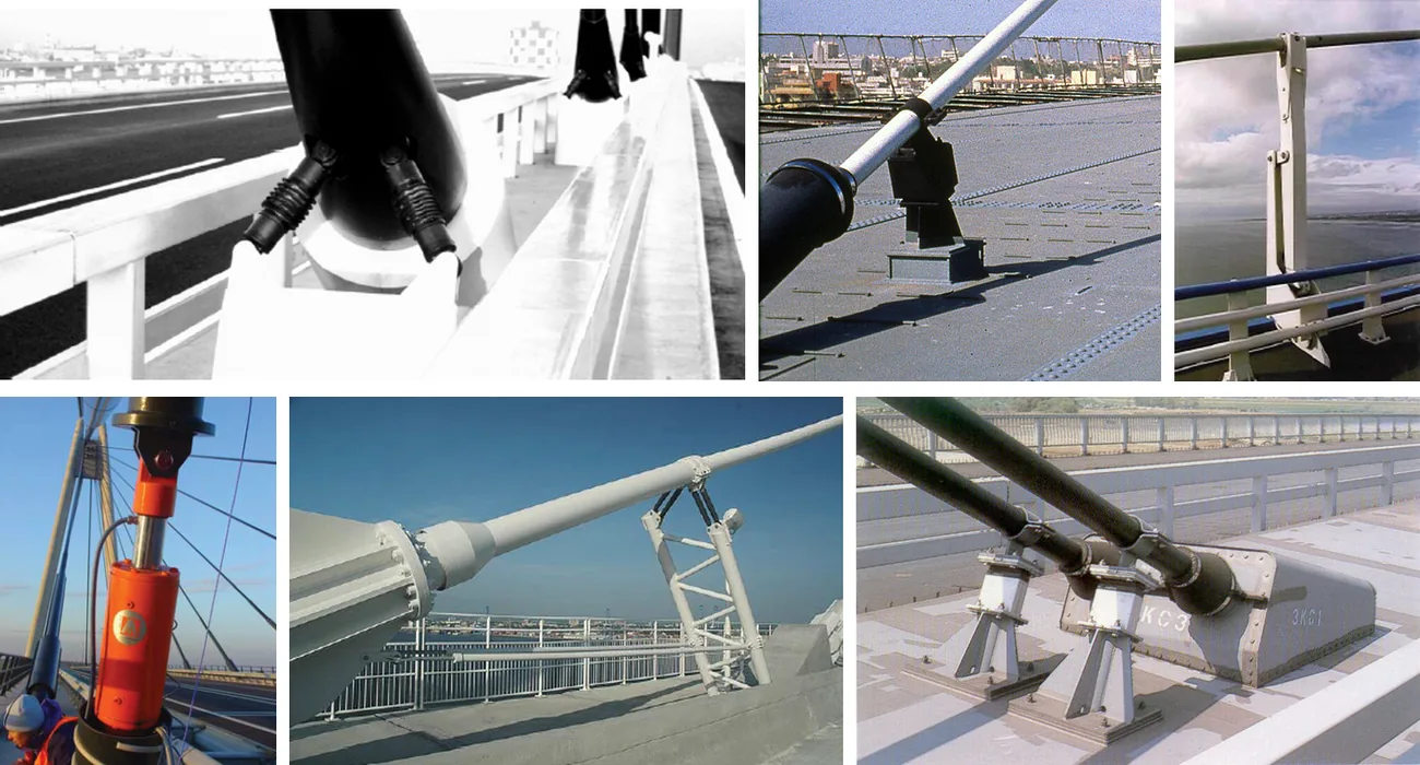
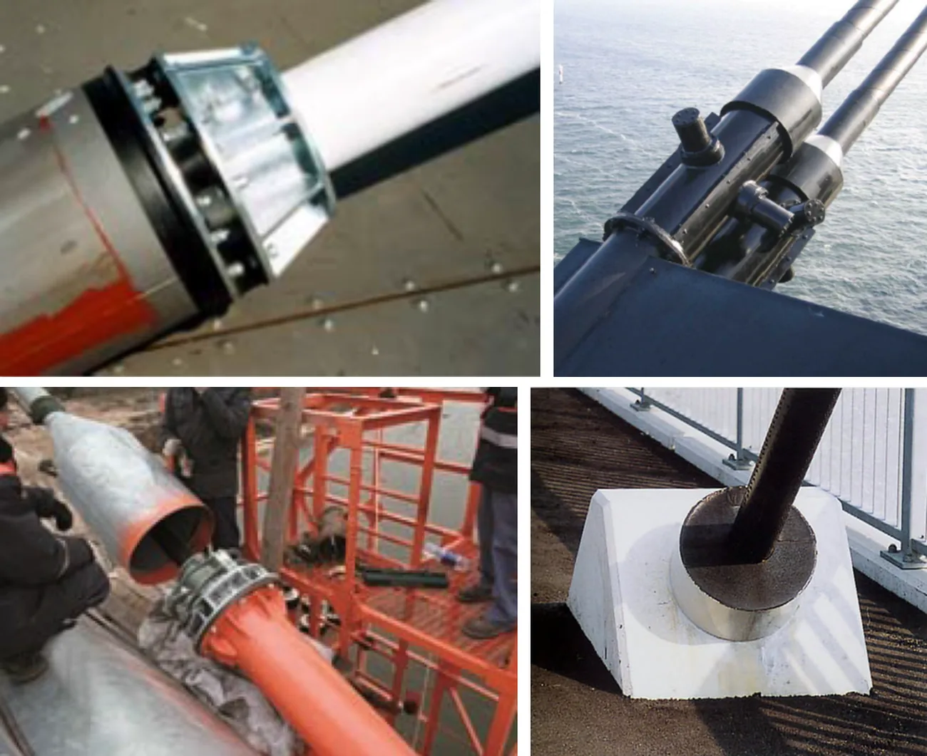
Damper types and their force laws: oil (viscous) dampers F = c·v; viscous shear dampers F = c·v + k·x; high-damping rubber F = k·x + f; friction or lead dampers F = μN. All dissipate energy as heat, and the area of the force and displacement loop shows how much. External dampers sit on a frame or strut above the deck, a few metres from the anchorage; internal dampers sit inside the guide pipe, close to the anchorage, where they are hidden but have a much smaller a/L. Semi-active (adaptive) dampers change their constant to suit the mode that is vibrating.
Cross ties
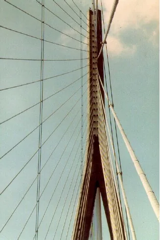
Cross ties (secondary cables) tie the stays of one plane together. They raise the frequencies of the stays by shortening their free length, which moves them out of the range of rain-wind and galloping, and they add a little damping through the tie network. They are effective on very long stays that dampers cannot reach, but the ties themselves must be designed against slackening and fatigue, and they change the look of the bridge.
Aerodynamic control: shaping the cable surface
The other way to stop rain-wind vibration is to stop the rivulets from forming or from moving. Several surfaces have been used: axial grooves or parallel strips along the cable, helical strakes or fillets wound round it, and fins. The two that dominate today are helical fillets and a pattern-indented (dimpled) surface on the HDPE pipe.
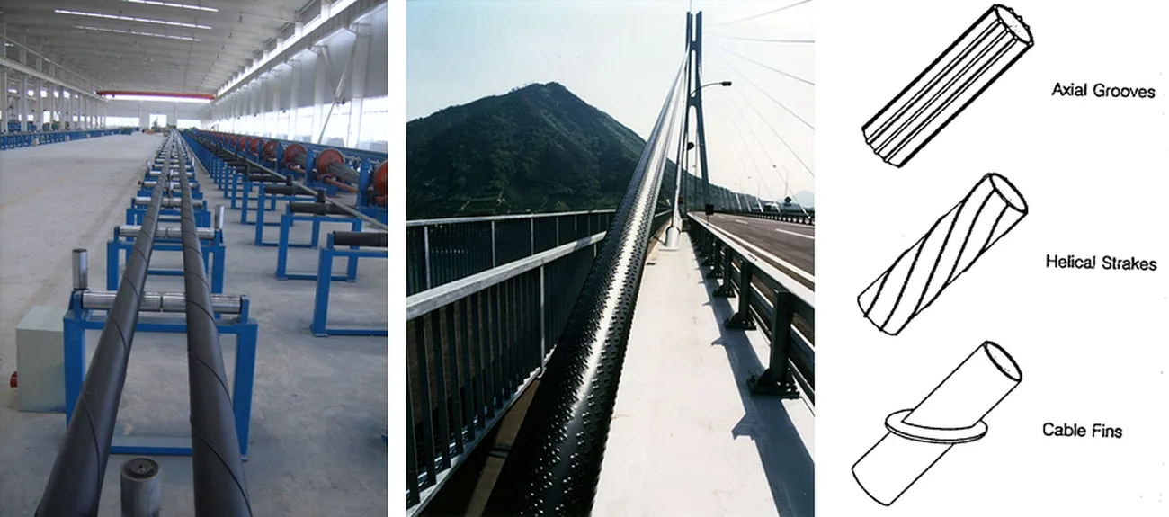
The surface also decides the wind load on the cable, which on long spans is a large share of the total wind load on the bridge:
with G the gust factor and A the projected area. On spans approaching 1,000 m the stays can attract as much wind load as the deck, or more, so a low drag coefficient C_D and a small diameter are worth as much as the vibration control. Drag coefficients of about 0.6 to 0.8 at design wind speeds are typical for good helical fillets and dimpled surfaces. The Tatara Bridge in Japan, with dimpled stays, was designed with C_D = 0.7.
A 2013 PhD study at the Technical University of Denmark (K. Kleissl, Cable Aerodynamic Control) compared the two systems in the same climatic wind tunnel, with and without artificial rain, and found:
- the pattern-indented surface trips the flow early and keeps a low, nearly constant drag at high Reynolds numbers, because its dimples create strong streamwise vortices;
- helical fillets give a smooth, gradual drop in drag, because the transition happens at different wind speeds along the span; their drag depends on the ratio of fillet size to cable diameter, so each cable size needs its own drag test;
- the cosine rule for skew wind does not hold for modified surfaces;
- the plain cable suffered severe rain-wind vibration and dry inclined galloping; neither modified cable showed severe rain-wind vibration, even though rivulets still formed on both;
- helical fillets in skew wind produced a lift force and a previously unreported limited-amplitude vibration in dry conditions as the flow changed regime;
- the surface energy of the HDPE, and therefore how water spreads on it, strongly affects whether rain-wind vibration occurs;
- among new surfaces, a helical pattern of cylindrical vortex generators reached a drag coefficient of only 0.58 but did not stop the rivulets; small triangular strakes wound helically removed the rivulets completely at a drag coefficient near 0.7, and the same strakes in a staggered helical arrangement brought it down to about 0.65.
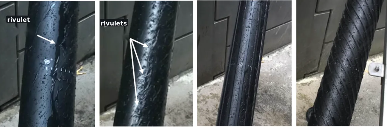
Larger protrusions work better against vibration but cost drag. The Higashi Kobe Bridge in Japan (485 m main span) used large parallel strips on its stays and needed no dampers, because the strips suppress both vortex and rain-wind vibration. The hangers of the Akashi Kaikyo Bridge were given helical wires after wake galloping was seen. To keep the benefit with less drag, flat helical strips (12 strips of 5 × 7.5 mm at 27° on a 50 mm model) were tested and gave a drag coefficient of about 0.6.
What long-span bridges use
| Bridge | Main span | Completed | Cable surface | Dampers |
|---|---|---|---|---|
| Russky Bridge, Russia | 1,104 m | 2012 | helical fillets | external and internal |
| Sutong Bridge, China | 1,088 m | 2008 | indented | external |
| Stonecutters Bridge, Hong Kong | 1,018 m | 2009 | indented | internal |
| Edong Bridge, China | 926 m | 2010 | helical fillets | yes (type not listed) |
| Tatara Bridge, Japan | 890 m | 1999 | indented | internal rubber |
| Pont de Normandie, France | 856 m | 1995 | helical fillets | external |
| Jingyue Bridge, China | 816 m | 2010 | helical fillets | yes (type not listed) |
| Incheon Bridge, Korea | 800 m | 2009 | indented | internal rubber |
Almost every long span combines a surface treatment against rain-wind vibration with dampers against the rest. At Tatara, the indented surface suppressed rain-wind vibration and rubber dampers controlled vortex vibration, which needed a logarithmic decrement of only about 0.01. Most other long-span bridges have required 0.03 or more, because of buffeting, dry galloping and deck and tower excitation, which surface treatment alone does not remove. High damping is hard to reach on very long cables because the damper's distance from the anchorage is limited, so it is effective and economical to use a combination of systems. Viscous materials may also not last as long as the cable, so dampers must be replaceable.
Bending fatigue at the anchorage
Whatever its cause, cable vibration bends the wires where the cable leaves the anchorage, and so does live load through the rotation of the deck. Bending fatigue tests under constant tension are standard, and biaxial fatigue tests (bending in two directions while the force cycles) are now increasingly required. The bending stress just in front of the socket is reduced by guiding the cable with elastic buffers at the end of the guide pipe, or by a bend limiter, a stiffened transition that spreads the curvature over a longer length. The spoke cables of the Ain Dubai observation wheel, which are cycled by the wheel's rotation, use elastic buffers for this reason. The bridge cables page explains the system fatigue tests.
Design case study: a long-span cable-stayed bridge
A vibration check of the stays of a long-span cable-stayed bridge in Korea at the design stage shows how the checks combine. The stays, numbered 1 to 66, had natural frequencies of 0.34 to 2.18 Hz and inherent damping of 0.03% to 0.20%; two stays had unusually large sag. Both strand cables and parallel wire cables were assessed.
- Vortex shedding. At the critical 10 to 15 m/s, the short strand cables (numbers 28 to 40) could lock in, but their higher inherent damping made them stable; the parallel wire cables were stable throughout.
- Rain-wind vibration. With an aerodynamic surface assumed on both types, the critical Scruton number was taken as 7.5. Every cable of both types fell below it, the strand cables much lower, so added damping was needed. Rain-wind vibration, the most common and dangerous case, became the basis of the design damping.
- Dry galloping. With c = 40 the onset speeds came out at 3 to 20 m/s for all cables. Because the formula is very conservative and dry galloping of round cables is still uncertain, it was left out of the governing cases.
- Deck excitation. Comparing the cable frequencies with the first five vertical bending modes of the deck (0.202 to 0.478 Hz) showed many cables close to resonance (n ≈ 1) but none at risk of parametric excitation, since the deck frequencies were well below the cable frequencies. Under the anchorage motion from a buffeting analysis at 15 m/s, several cables exceeded the amplitude limit, two of them by more than three times.
- Dampers. Internal dampers in the guide pipes, 0.95 m from the anchor plate, could not reach the required damping and did almost nothing for deck excitation. External oil dampers 2.5 m above the deck met the rain-wind requirement on every cable and cut the number of cables over the amplitude limit sharply.
- What was left. Two cables still exceeded the limit. They needed 1.91% and 3.28% damping, which would have meant external dampers 4.8 m and 8.5 m above the deck, not practical. The answer for those cables was dampers at the tower end or cross ties.
The conclusions are typical of long-span stays: parallel wire cables behave slightly better aerodynamically, but with external dampers the difference from strand cables is small; dampers must be external to be effective; the design damping can be based on rain-wind vibration; and deck-induced vibration of a few cables cannot be solved by deck-level dampers alone.
Measuring cable force and damping on site
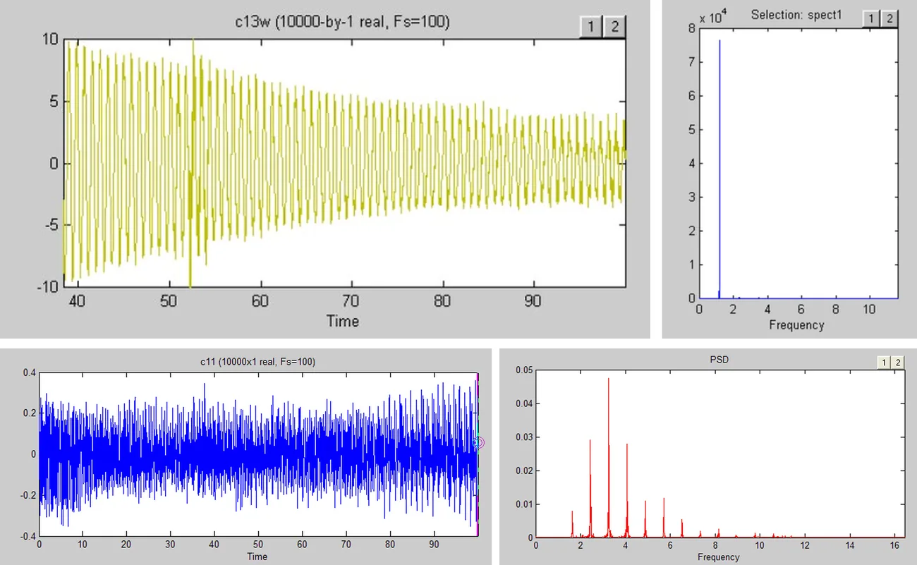
The vibration of a cable is also the easiest way to measure its force and its damping.
- Excite the cable. By hand, pulling a rope to excite a single mode, with a mechanical exciter clamped to the cable for a chosen mode and amplitude, or simply by recording the ambient vibration from wind and traffic.
- Measure. Accelerometers clamped to the cable are the usual choice; displacement sensors at the deck are an alternative.
- Analyse. The spectrum (FFT) of the record gives the natural frequencies, and from them the force. The decay of the free vibration after the excitation stops gives the damping. Measure damping in still air so that aerodynamic damping does not inflate it.
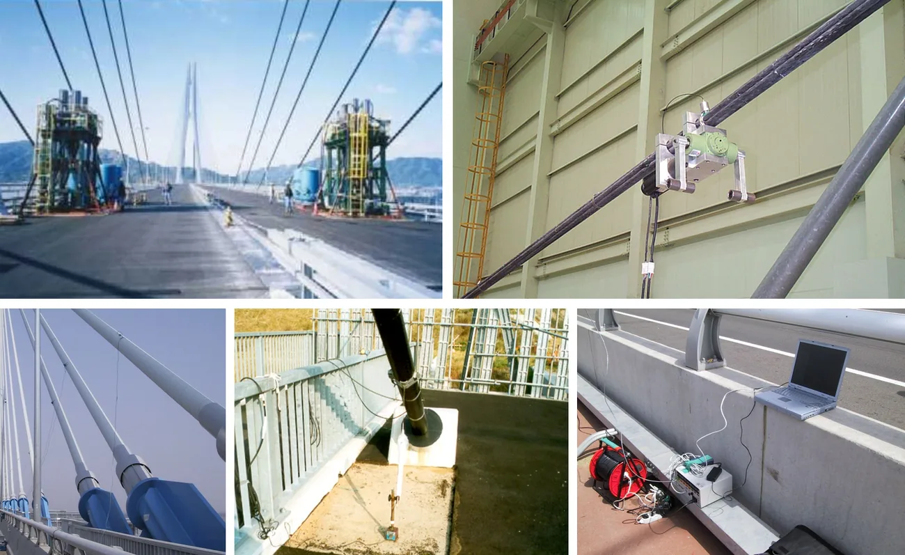
Force from one mode. For a single excited mode the taut string gives T = 4 m L² (fₙ / n)². Example: a stay 97.7 m long with m = 76.2 kg/m and a first mode at 1.17 Hz carries T = 4 × 76.2 × 97.7² × 1.17² ≈ 3,983 kN (about 406 tonnes).
Force from many modes. With ambient vibration many modes appear at once. Bending stiffness raises the higher modes, so the frequencies are fitted with
A straight line through the measured points gives the force from the intercept and the effective bending stiffness from the slope. Sag lifts the lowest symmetric modes above the line, so only the higher modes are used for the fit. The free length L must be measured between the effective fixing points: dampers and guide pipe bushings shorten it.
Damping from the decay. The envelope of the free decay is a(t) = A ω² e^(−ξωt). Plotting the natural logarithm of the envelope against time gives a straight line of slope −ξω, so ξ = −slope / ω. For a cable at 1.17 Hz (ω = 7.35 rad/s), a fitted slope of −0.0211 per second gives ξ ≈ 0.29%.
A checklist for designers and owners
- Compute the natural frequencies of every stay and hanger at every construction stage and in service, including sag.
- Check vortex shedding, rain-wind (Scruton number), dry galloping, wake galloping and deck and tower excitation for every cable, and state which definition of the Scruton number is used.
- Specify the cable surface by its tested drag coefficient and its rain-wind performance at the actual cable diameter, not by a generic shape.
- Set the design damping per cable, choose the damper type and its distance from the anchorage, and check the a/L ceiling before relying on a damper for very long cables.
- Provide space and access at both ends of the longest cables for dampers or cross ties if they are needed later.
- Check the cable amplitude against L/1600 and the anchorage rotation limit, and the bending fatigue at the anchorage.
- Measure frequencies, forces and damping of every cable at completion, with and without dampers, and keep them as the baseline for the life of the bridge.
Related on TheBridgeEng
Questions engineers ask
- What is rain-wind induced vibration of stay cables?
- A large-amplitude vibration of inclined stay cables in light to moderate rain and wind of about 8 to 15 m/s. Rivulets of water on the cable surface change its aerodynamic shape and oscillate with the cable, which can then vibrate by a metre or more, mostly in its second or third mode. It is the most common stay cable vibration.
- What is the Scruton number of a cable?
- Sc = m ξ / (ρ D²), the mass per metre times the damping ratio divided by the air density times the diameter squared. PTI recommends Sc of at least 10 against rain-wind vibration. Some documents use the logarithmic decrement instead of the damping ratio, which gives values about 4π times larger.
- How much damping can a stay cable damper add?
- For a damper at distance a from the anchorage of a cable of length L, the added damping in any mode is at most about 0.5 a/L, reached when the damper constant is tuned to that mode. A damper 2 m from the anchorage of a 100 m cable can give up to about 1%, but only about 0.25% on a 400 m cable.
- Why do stay cables have helical fillets or dimples?
- The surface pattern stops water rivulets from forming or moving, which suppresses rain-wind vibration, and keeps the drag coefficient low, about 0.6 to 0.8 at design wind speeds, which reduces the wind load on the cables, towers and deck.
- How is cable force measured from vibration?
- Accelerometers record the cable vibration and a spectrum gives its natural frequencies. For a taut cable T = 4 m L² (fn/n)². With several modes, (fn/n)² is plotted against n² and a straight line fitted through the higher modes: the intercept gives the force and the slope the bending stiffness.
Updated 2026-11-04 · written by a practising bridge engineer