Bridge topics · Expert session
Bridge Cables: PWS, Multi Strand, Locked Coil and Spiral Strand
Parallel wire strands, multi strand cables, locked coil and spiral ropes and bars: how bridge cables are made, anchored, protected, tested, installed and measured, and how to choose between them.
Cables carry the deck of every cable-stayed, extradosed and suspension bridge, the hangers of tied arches and the tension members of many footbridges and roofs. They are usually only a few percent of the cost of a bridge, yet they decide its stiffness, its fatigue life, how fast it can be built and what has to be replaced first. This page is an expert session on bridge cables: the families of tension elements, how parallel wire, parallel strand and spiral rope cables are made and anchored, how they are protected, tested, installed and measured, and how to choose between them as a designer or as an owner.
The families of tension elements
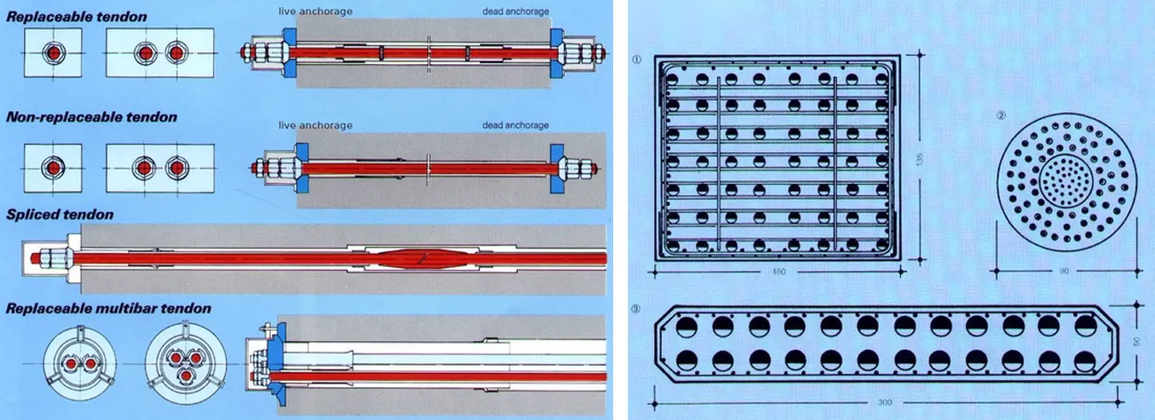
Eurocode EN 1993-1-11, the code for structures with tension components, groups bridge cables into three families. The grouping is useful because it follows how the steel is arranged, and that decides stiffness, fatigue behaviour and the type of anchorage.
| Group | What it is | Examples | Typical bridge use |
|---|---|---|---|
| A | Solid bars | high-strength threaded bars, multibar tendons | short stays and ties, arch hangers, temporary stays, anchor rods |
| B | Wire ropes: wires twisted in layers | open spiral strand (OSS), full locked coil (FLC), stranded ropes | hangers, footbridge cables, main cables of smaller suspension bridges, early stay cables |
| C | Bundles of parallel wires or strands | parallel wire strand (PWS), multi strand cables of 7-wire strands, the main cables of large suspension bridges | stay cables, extradosed cables, suspension main cables and hangers |
The more the steel is twisted, the more the cable stretches under load before the wires take their full share, so twisted ropes are less stiff than parallel bundles. Parallel elements need anchorages that grip every wire or strand equally, which is the whole art of a stay cable system.
The steel inside the cable
Almost every bridge cable is made of cold-drawn, high-carbon steel wire. The difference between cable types is mostly how those wires are grouped.
- Bridge wire for parallel wire cables is 5 mm or 7 mm in diameter, galvanised, with a tensile strength of 1570, 1670 or 1770 MPa. Long-span suspension bridges have pushed this to about 1800 MPa (Akashi Kaikyo) and 1860 to 2000 MPa on recent Chinese bridges, which saves cable weight where the cable's own weight is most of the load.
- Prestressing strand for multi strand cables is a 7-wire strand of 15.2 or 15.7 mm (about 140 or 150 mm²) at 1860 MPa, low relaxation, individually galvanised, waxed and sheathed in HDPE for stay cable use. A 15.7 mm strand breaks at about 265 to 279 kN depending on the standard.
- Rope wire for spiral strands is round, or Z-shaped in the outer layers of a locked coil rope, galvanised or coated with Galfan (a zinc and 5% aluminium alloy that resists corrosion better than plain zinc). Stainless wire is used for small architectural ropes.
- Bars are hot-rolled alloy steel, with a yield strength of about 835 to 1080 MPa and a tensile strength of about 1030 to 1230 MPa, threaded at the ends.
The strength that matters in design is not the strength of the steel but the guaranteed breaking load of the whole cable (often written GUTS or MBL) and the capacity of the anchorage that has been proven by testing. A cable is only as good as its weakest end.
| Element | Elastic modulus | Steel strength | Size range (indicative) |
|---|---|---|---|
| Parallel wire strand | about 195 to 205 GPa | 1570 to 1770 MPa (higher grades available) | from a few tens to several hundred wires |
| Multi strand cable | about 195 GPa | 1770 to 1860 MPa | from a few strands to well over a hundred |
| Full locked coil | about 160 GPa | 1570 to 1770 MPa wire | about 20 to 140 mm, breaking loads up to about 20 MN |
| Open spiral strand | about 150 GPa | 1570 to 1770 MPa wire | about 6 to 36 mm (19 to 91 wires), up to about 1.2 MN |
| Bars | about 205 GPa | 835 to 1080 MPa yield | about 18 to 75 mm |
Long stays also sag under their own weight, so their effective stiffness is lower than the steel modulus. The Ernst equivalent modulus accounts for this; the stay-cable catenary tool works it out for a given cable, span and stress.
Parallel wire strand (PWS) cables
A parallel wire strand is a bundle of galvanised 5 mm or 7 mm wires laid in a hexagon, given a very slight twist (a lay angle of a few degrees, under about 4°) so the bundle holds together and can be coiled on a reel, wrapped in a polyester filament tape and extruded with a high density polyethylene (HDPE) jacket, usually two layers, a black inner layer for UV resistance and a coloured outer layer. Jacket thickness is typically 5 to 17 mm depending on the size. The same product is called a prefabricated parallel wire cable, a PE-shelled large pitch twisted cable, or in PTI terms a pre-assembled cable with HDPE.
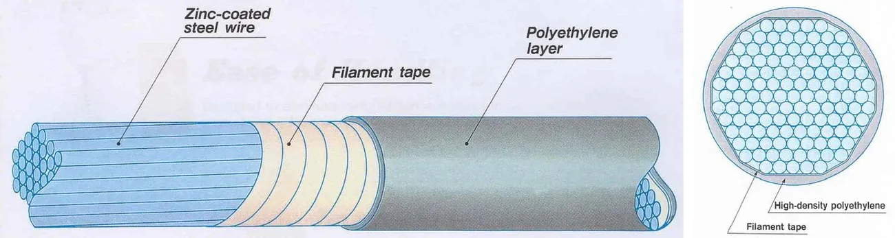
The cable is made to a fixed length in the factory. The wires are cut to length under a controlled reference tension, the sockets are fitted, and the finished cable is coiled on a reel or drum. Because everything is done indoors, the length, the force sharing between wires and the corrosion protection can be controlled and checked before the cable leaves the factory.
PWS anchorages: hot and cold sockets
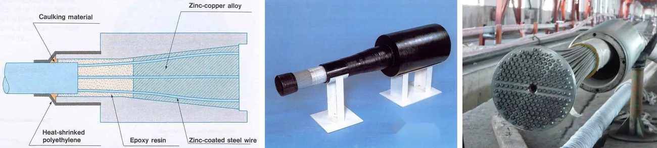
The wires are spread inside a conical steel socket and locked in by a cast filling. Two systems are used.
- Hot socket. The wires are broomed out in the socket and molten zinc-copper alloy is poured in. The cone grips the wires by friction and wedging. This is the traditional rope socket and is still used for spiral ropes and many PWS cables.
- Cold socket. Each wire is passed through a perforated anchor plate and given a cold-formed button head, and the cone is filled with a mix of steel balls, zinc dust and epoxy resin. The button heads hold the wires and the filling transfers load gradually along the cone, which gives a much better fatigue performance. This is the high-amplitude (HiAm) type of anchorage developed for stay cables.
The socket is threaded on the outside and carries a ring nut that bears on the anchor plate, so the cable can be adjusted by turning the nut, or by pulling on an extension rod screwed into the socket with a centre-hole jack. The transition from socket to cable is sealed with a heat-shrink sleeve over the HDPE.
Strengths and limits of PWS
- Compact: no gaps between wires and jacket, so the cable is the smallest possible for its strength and the wind load on it is the lowest.
- Factory quality: wire lengths, force sharing and the seal between steel and jacket are made and inspected in the factory.
- Fast installation: the cable arrives complete; lifting, pulling in and stressing one cable is a matter of hours.
- Small anchorages, which suits slender pylons and tight anchor zones, and one jack stresses the whole cable.
- Heavy: a long stay can weigh tens of tonnes, so it needs a reel stand, unreeling equipment and a large winch or crane, and transport to site must be planned, usually by barge for over-water bridges.
- Fixed length: the length must be right before fabrication, so the geometry control and the survey of the as-built pylon and deck must be done well in advance.
- Replaced as a whole: individual wires cannot be changed, and a damaged cable means a new cable from the factory, with the lead time that goes with it.
Multi strand (MS) cables
A multi strand cable, also called a parallel strand cable, is a bundle of 7-wire prestressing strands laid parallel inside an HDPE duct. Each strand has its own protection: galvanised wires, a wax or grease filling in the interstices and a tight HDPE sheath extruded over it, so each strand is a protected tendon on its own. The outer duct, often with a helical fillet on its surface against rain-wind vibration, mainly protects the bundle from impact and sunlight and gives the cable its appearance. Cable sizes run from a few strands to more than a hundred.

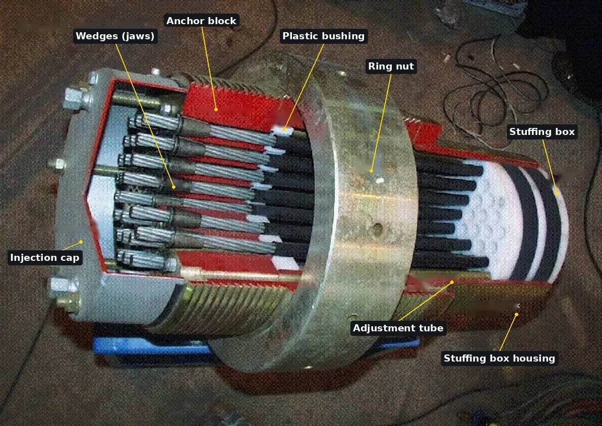
MS anchorages: wedges, ring nut and stuffing box
The strands are anchored one by one in a steel anchor block with conical holes and two- or three-part wedges, as in post-tensioning, but with details for fatigue: the strand sheath is stripped only where it enters the anchorage, the wedges are chosen and seated for cyclic loading, and the zone where strands leave the block is filled with wax or grease. Behind the block a stuffing box seals the strand bundle and the bushing at the end of the guide pipe holds the strands in position so bending at the anchorage is kept low. The block is threaded and carries a ring nut, so the whole cable can be adjusted later with a multi-strand jack.
Strengths and limits of MS
- Light equipment: a coil of strand weighs a few tonnes and the jack can be carried by two people, so cables are installed without heavy lifting, which suits bridges with poor access or very long stays.
- Replaceable and inspectable strand by strand: a single strand can be lifted off to check its force, taken out for inspection or replaced under traffic, without removing the cable.
- No fixed length in advance: the strands are cut on site, so the cable adapts to the as-built geometry.
- Larger diameter: the strands are round and individually sheathed and need clearance to be threaded into the duct, so the duct is roughly 1.3 to 1.6 times the diameter of a PWS cable of the same strength. Compact ducts reduce, but do not remove, the difference.
- Site quality: the cable is assembled in the open, strand by strand, so the wedges, the sheath stripping, the force sharing and the filling of the anchorage depend on the crew and the weather.
- More time on site: installation typically takes longer than for a factory-made cable, and the anchorages are larger.
Spiral ropes: open spiral strand and full locked coil
Spiral ropes are made of wires twisted in layers around a core, each layer in the opposite direction to the one below, so the rope does not untwist under load. They are made to length with their end fittings, like PWS cables, and are fully finished products, but their twist makes them less stiff.
- Open spiral strand (OSS) is built of round wires, typically 19 to 91 of them, in sizes of about 6 to 36 mm and breaking loads up to about 120 tonnes. Galfan-coated or stainless wire is normal, because the open surface lets water in between the wires. It is the usual choice for hangers of small suspension and arch footbridges and for architectural tension members. The Eunpa pedestrian suspension bridge in Korea uses open spiral strands for its hangers.
- Full locked coil (FLC) has a core of round wires and two or more outer layers of Z-shaped wires that interlock. The locked outer layers form a closed surface that keeps water out and protects the inner wires from local damage, which made FLC the most watertight and durable cable before separate jackets came into use. Sizes run from about 20 to 140 mm, with breaking loads up to about 2000 tonnes. FLC has been used for stay cables, hangers and the main cables of smaller suspension bridges; in Korea, the Jindo and Dolsan bridges have FLC main cables.
Spiral ropes have an elastic modulus of about 150 to 160 GPa, roughly 20% below parallel wires, and they show a larger permanent elongation the first time they are loaded. They are therefore pre-stretched in the factory and measured and marked under a defined tension, so the length on site is known.
End fittings for spiral ropes
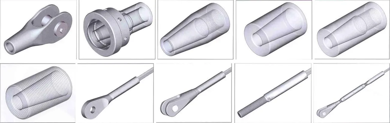
Locked coil ropes are anchored in cast sockets filled with zinc-copper alloy, with many shapes for different connections: open (fork) sockets with a pin, closed (eye) sockets, cylindrical sockets with an external thread and ring nut, and sockets adjusted with shims. Small open spiral strands use swaged fittings, where a steel sleeve is pressed onto the rope, ending in a fork, an eye or a threaded rod. The type of socket decides how the tension is adjusted: by turning a nut, adding shims or turning a turnbuckle.
Bars and multibar tendons
High-strength bars are the stiffest and simplest tension element. A bar is threaded at the ends and anchored with a nut on a bearing plate, can be coupled to extend it and is easy to adjust and to replace if it is installed in a sheath. Single bars and bundles of bars (multibar tendons) are used for short stays, arch hangers, ties and temporary stays during erection, and as the anchor rods that tie cables into the ground. Their weak points are the threads and couplers, which have a much lower fatigue strength than the plain bar, so bars are best where the stress range is small.
PWS or MS: a side-by-side comparison
For stay cables the real choice is usually between parallel wires and parallel strands. Both are mature, both have carried record spans, and suppliers of each tend to describe the other unfairly. The table below sets out the differences that actually decide a project.
| Topic | Parallel wire strand (PWS) | Multi strand (MS) |
|---|---|---|
| Where the cable is made | In a factory, to length, with its sockets | On site, strand by strand, inside the duct |
| Diameter for the same strength | Smallest (no gaps) | About 1.3 to 1.6 times larger (duct clearance) |
| Wind load and appearance | Lower drag, slimmer look | Higher drag on cable, pylon and deck; compact ducts help |
| Anchorage | Small cast socket with ring nut; good fatigue with cold-cast filling | Larger wedge anchorage with ring nut and stuffing box |
| Corrosion protection | Heavy galvanising, tape, double HDPE jacket, all applied in the factory | Galvanising, wax and sheath on each strand, plus the outer duct; anchorage filled with wax or grease on site |
| Installation equipment | Reel stand, unreeler, winch or crane for the whole cable | Light winch, shuttle and monostrand jack |
| Installation time | Short, one cable at a time | Longer, one strand at a time |
| Stressing | One centre-hole jack for the whole cable | Each strand to an equal force, then the whole cable with a multi-strand jack if needed |
| Inspection | Jacket visible over the full length; magnetic flux testing possible through the jacket | Strand sheaths hidden in the duct; individual strands can be lifted off and withdrawn for inspection |
| Replacement | Whole cable only | Strand by strand, or the whole cable |
| Length | Must be fixed before fabrication | Cut on site to the as-built geometry |
| Supply | Few specialist factories (mainly Japan, China, Korea); transport of reels | Several international stay cable system suppliers; strand widely available |
| Examples | Tatara (Japan), Machang and Incheon bridges (Korea) | Normandie and Millau (France), Russky (Russia), Seohae Bridge (Korea) |
Corrosion protection, layer by layer
A cable is a large number of thin, highly stressed wires, and corrosion of a highly stressed wire can lead to brittle fracture with very little warning. Modern stay cables therefore have several independent barriers, so that one damaged layer does not expose the steel.
| Barrier | PWS | MS |
|---|---|---|
| On the wire | Heavy hot-dip galvanising, around 300 g/m² | Galvanising on each wire of the strand, around 190 g/m² or more |
| Filling | None needed: the jacket is extruded tight on the taped bundle, so no air or water is trapped | Wax or grease filling the voids inside each strand |
| Sheath | Polyester tape and double HDPE jacket over the whole bundle | HDPE sheath on each strand, about 1.5 mm thick |
| Outer layer | The jacket itself | HDPE duct, with air around the strands (it protects against impact and UV, not against condensation) |
| Anchorage | Cast filling (zinc alloy or epoxy with steel balls), sealed by a heat-shrink sleeve; tested for watertightness | Wax or grease in the anchorage and a grease-filled cap; the wedge bite removes the zinc locally |
The weak points are the same for every system: the lower anchorage, where water runs down the cable, and the transition from the free length into the guide pipe. Good details drain the lower anchorage, seal the top of the guide pipe with a boot, keep the anchorage cap accessible and avoid water traps at the deck.
The worst corrosion cases come from an earlier generation. Many stay cables of the 1970s and 1980s, both wire and strand types, were bundles of bare steel inside a polyethylene pipe filled with cement grout. The grout cracked under live load and temperature, early polyethylene was not stabilised against UV and split, and water reached the steel. Several of those cables had to be replaced after a short life. Today's systems, with individually protected strands or factory-jacketed wire bundles, are tested for watertightness, and HDPE jackets are qualified by artificial ageing tests, so the old failures should not be used to judge the current products of either type.
Fatigue and system testing
A stay cable sees millions of stress cycles from traffic and wind. The steel itself has a good fatigue strength in a plain tensile test; the weak points are always where the wires are held: the wedge teeth biting into a strand, the button head or cast filling at the end of a wire, and the bending of the wires where the cable leaves the anchorage. For this reason a stay cable is accepted only as a complete system, anchorage and cable together, tested as specified in the fib recommendations (fib Bulletin 30, now Bulletin 89) and the PTI recommendations (PTI DC45.1).
- Fatigue test of the system: a full-scale or representative specimen with both anchorages, cycled two million times with an upper stress of 45% of the guaranteed breaking strength and a set stress range (200 MPa in the fib test), with an angular deviation of about 10 mrad at the anchorage to simulate bending. The number of broken wires is counted.
- Residual strength test: the same specimen is then pulled to failure and must reach a high share of the actual breaking load of its steel, so that the fatigue cycles have not weakened it.
- Leaktightness test: the anchorage and the cable transition are bent, cycled and immersed under water pressure to prove that water cannot reach the steel.
- Tests on the components: fatigue tests on single wires and strands (higher stress ranges than the system), wedge and socket efficiency tests, HDPE material and ageing tests.
Both PWS and MS systems pass these tests when they are made properly. In service, the margin comes from the details on the drawings: keeping bending out of the anchorage with deviators and bushings, keeping the guide pipe straight on the cable axis and keeping the stress range within what was tested.
Wind and rain vibration
Stay cables are long, light and lightly damped, with an inherent damping of often only 0.1% to 0.3% of critical, so they vibrate easily. The mechanisms are different and need different cures.
- Rain-wind vibration: in moderate wind with light rain, water rivulets on the upper and lower surface of the cable change its shape and it can oscillate with amplitudes of a metre or more. This is the most common problem on stays. Cures are a surface that breaks up the rivulet (a helical fillet on the HDPE, or dimples) and added damping.
- Vortex shedding: small amplitudes in steady wind, at high modes; usually controlled by the cable's own mass and damping.
- Dry galloping and wake effects: large inclined cables, and cables standing in the wake of other cables or of the pylon, can become unstable at high wind speeds.
- Parametric excitation: when the deck or pylon moves at about twice a cable frequency, the change in cable force pumps energy into the cable. This is a matter of tuning the cable and deck frequencies.
PTI uses a mass-damping (Scruton) number, Sc = mζ / (ρD²), with m the mass per metre, ζ the damping ratio, ρ the air density and D the diameter, and recommends a value of about 10 or more against rain-wind vibration on cables without a surface treatment. A smaller diameter helps twice: it lowers the wind load and raises the Scruton number. Damping is added with dampers at the deck end, internal (in the guide pipe) or external (on a strut), placed at a few percent of the cable length from the anchorage; very long stays may also need cross-ties between cables. Allow for dampers in the design from the start, for both PWS and MS, rather than as a repair.
Measuring the cable force
The force in each stay has to be set during construction and checked during the life of the bridge. Three methods are used.
- Lift-off: a jack is put on the anchorage and pressure is raised until the nut, or a single strand's wedges, just lifts off. Direct and reliable, but slow, and it needs access and a jack at each anchorage.
- Load cells: a ring load cell under the anchor nut, or on a reference strand in an MS cable, gives a continuous reading. Used on a few cables per bridge for monitoring, because they are costly and must be built in.
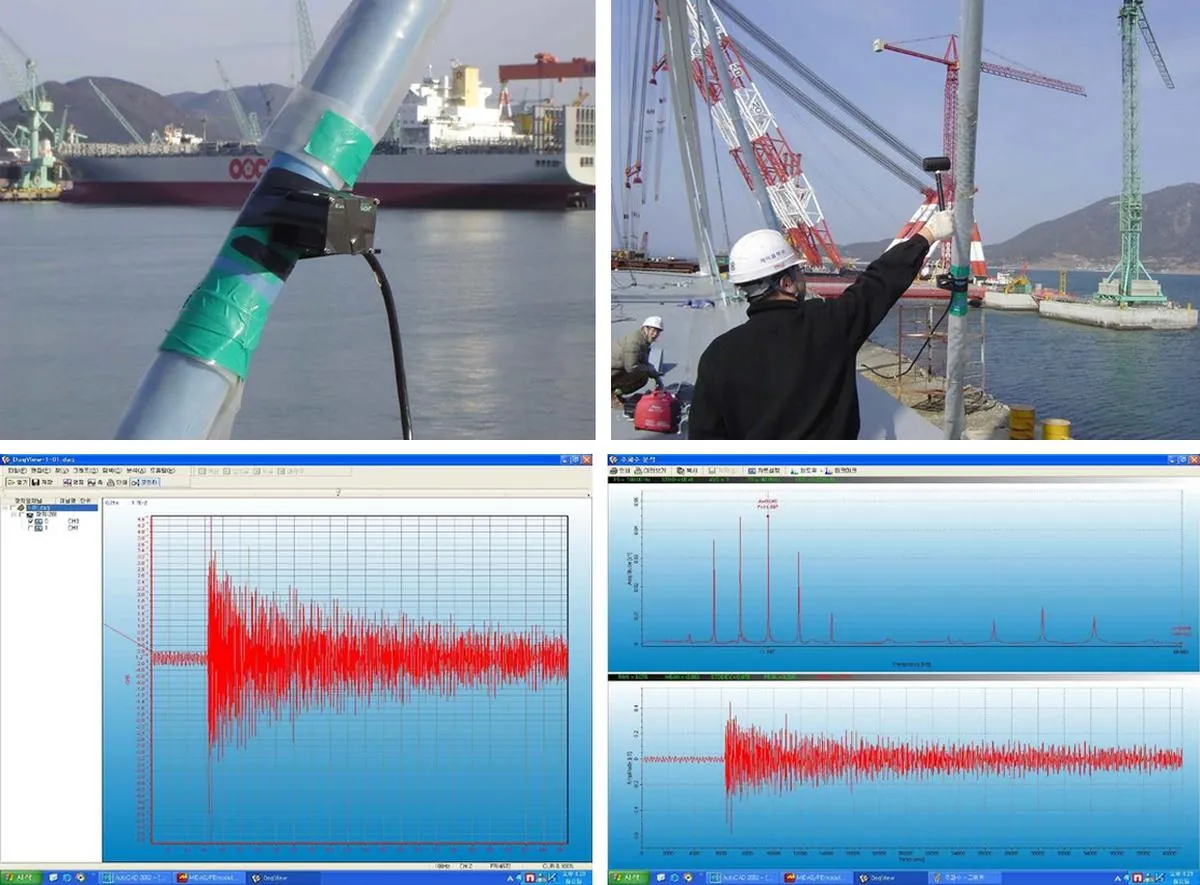
- Vibration (frequency) method: an accelerometer is strapped to the cable, the ambient vibration is recorded and the natural frequencies are found by spectral (FFT) analysis. For a taut string, the force follows from the frequencies:
The method is quick, needs no contact with the anchorage and can cover every cable of a bridge in a day. Its accuracy depends on knowing the true free length between the effective fixing points (the dampers and guide pipes shorten it) and the mass, and on corrections for bending stiffness and sag, which matter for short, stiff or very long cables. Calibrate it once against lift-off or load cells, then use it for the rest. It is used on PWS cables, where the steel and the jacket vibrate as one, and also on MS cables, where the strand bundle and the duct are less tightly coupled and the reading needs more care.
Installation and stressing
The two stay systems are installed in very different ways, and the choice often decides the erection equipment on the deck and the pylon. The stay cable installation method page follows the full erection cycle; here are the essentials.
PWS cables arrive on reels. The reel is set on a turntable on the deck, the upper socket is connected to a pulling rope from a winch in the pylon, and the cable is unreeled and pulled up while a crane or derrick supports it to avoid sharp bends. The upper socket is drawn into its anchor tube in the pylon, the lower socket is fixed at the deck, and a single centre-hole jack, often working on an extension rod screwed into the socket, stresses the cable and the nut is turned down. With short cables on land bridges, a truck and a mobile crane may be enough; long cables over water come by barge.
MS cables start with the HDPE duct, which is welded to length on the deck and lifted with the first strand inside it. That first strand is anchored and stressed and becomes the reference. Each following strand is pulled up through the duct by a shuttle on a winch line, anchored and stressed with a light monostrand jack so that its force matches the reference strand at that moment, using a load cell on the reference strand. Done correctly, all strands end with the same force even though the structure deforms as the cable is built up. Final adjustments of the whole cable are made with a multi-strand jack on the ring nut.
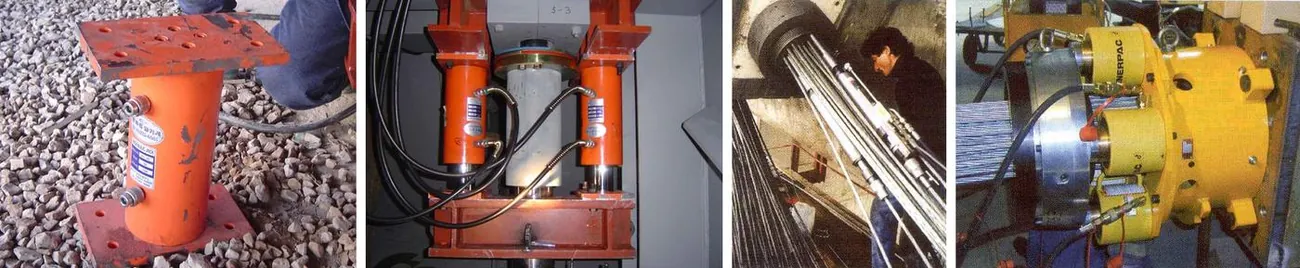
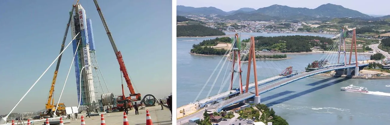
Either way, the cable forces are set in steps that follow the construction stage analysis, and the final forces and the deck profile are checked against the geometry control model. On a bridge with many stays, the vibration method is the quickest way to confirm the forces of all cables at the end of each stage.
Design numbers worth remembering
- Stay cables, service: maximum force about 45% of the guaranteed breaking strength (PTI and fib), with higher limits for construction stages and for accidental cases such as the loss or replacement of a cable.
- Extradosed cables: higher allowable stress, around 60% of breaking strength, accepted because their stress range is small; the extradosed bridge page explains the limits.
- Suspension main cables: factor of safety of about 2.0 to 2.5 against the breaking strength of the wires (2.2 at Akashi Kaikyo), lower than for stays because the live load is a small part of the total and the stress range is low.
- Cable loss: the structure must survive the sudden loss of any one stay. In a static analysis PTI applies a dynamic factor of 2.0 to the force of the lost cable; a time history analysis may justify less.
- Cable replacement: each stay must be replaceable with the bridge in service under a reduced traffic load, which sets the size of the anchorages, the access and the space for jacks.
- Stress range: check the fatigue stress range of every stay against the tested range of the system, including bending near the anchorages.
Inspection and maintenance
- Visual inspection of the jacket or duct over the full length, by robot or rope access, looking for splits, scratches and loose fillets; PWS jacket damage can be repaired by welding or wrapping on site.
- Anchorages: open caps at intervals, check for water, corrosion and the condition of the wax or grease, and refill it properly afterwards. Keep the lower anchorages drained.
- Forces: vibration measurements of all cables every few years and after events, compared with the as-built values; lift-off on selected anchorages or strands.
- Non-destructive testing: magnetic flux leakage devices can detect broken wires and loss of section through a PWS jacket. In MS cables, strands can be withdrawn and examined.
- Dampers and boots: check the dampers, neoprene boots and guide pipe seals, which wear faster than the cable.
- Dehumidification: for suspension main cables, dry air injected under the wrapping keeps the humidity below the level at which the wires corrode; see cable dehumidification.
How to choose
- Slender pylon, tight anchorage zones, strong wind or a strict appearance requirement: PWS, for the smaller cable and anchorage.
- Poor access, no heavy lifting on the deck or pylon, very long stays: MS, which is installed with light equipment.
- Programme is critical: PWS installs faster on site, if the fabrication slot, the length data and the transport are secured early.
- Owner wants inspection and replacement without closing the bridge: MS, which can be checked and replaced strand by strand; PWS needs a full replacement plan from the start.
- Extradosed bridges with saddles in the pylon: usually strand systems, with individual strand saddles that let strands be replaced one at a time.
- Hangers of arches and small suspension bridges, footbridges: spiral strands or locked coil ropes, or PWS for larger forces; bars where the members are short and the stress range is low.
- Large suspension main cables: parallel wires, by air spinning or prefabricated strands; see suspension bridge cable erection.
A checklist for the owner and the designer
Cable packages are often specified by performance and awarded to a specialist subcontractor, so the specification must close the gaps that suppliers' brochures leave open.
- Name the acceptance standard (fib or PTI, with edition) and require system qualification tests that cover the actual cable sizes and the actual anchorage, including bending and leaktightness.
- Require factory production control, mill certificates for every heat of wire or strand, and witness tests on samples taken from production.
- Specify the corrosion protection layer by layer, including galvanising mass, filling material, sheath and jacket thickness and the HDPE ageing requirements, and how the anchorage zone is sealed and drained.
- Fix the design life of each component, and which parts are replaceable: cable, strand, damper, boot, cap.
- Specify the aerodynamic measures: surface treatment, damping targets per cable, provision for dampers and cross-ties.
- Define the force tolerances, the stressing procedure and how forces are checked at each stage and at handover, including the calibration of the vibration method.
- Ask for the replacement procedure and the cable loss analysis at design stage, with the space and fixing points for jacks and temporary supports shown on the drawings.
- Agree the inspection and monitoring plan and hand over as-built forces, frequencies and anchorage data as the baseline for the life of the bridge.
Related on TheBridgeEng
Questions engineers ask
- What is the difference between PWS and multi strand stay cables?
- A parallel wire strand (PWS) cable is a bundle of 5 or 7 mm wires made to length in a factory with an HDPE jacket and cast sockets, installed and stressed as one piece. A multi strand cable is built on site from individually sheathed 7-wire strands threaded into an HDPE duct and anchored one by one with wedges. PWS is smaller and faster to install; multi strand needs only light equipment and can be inspected and replaced strand by strand.
- What is a full locked coil cable?
- A spiral rope with a core of round wires and outer layers of Z-shaped wires that interlock to form a closed surface. The locked layers keep water out, so the rope is durable without a separate jacket. It is used for hangers, stays of smaller bridges and the main cables of smaller suspension bridges.
- How is the force in a stay cable measured?
- By lift-off with a jack at the anchorage, by load cells built in under the anchor nut or on a reference strand, or by the vibration method, where the natural frequencies are measured with an accelerometer and the force is calculated as T = 4 m L squared times (fn / n) squared, with corrections for bending stiffness and sag.
- What is the allowable stress in a stay cable?
- Under service loads PTI and fib limit the force to about 45% of the guaranteed breaking strength, with higher limits for construction and accidental cases. Extradosed cables are allowed about 60% because their stress range is small, and suspension main cables use a factor of safety of about 2.0 to 2.5.
- Why do stay cables vibrate in rain?
- Light rain in moderate wind forms rivulets on the cable surface that change its aerodynamic shape, which can make long stays oscillate strongly. Helical fillets or dimples on the HDPE surface and dampers near the deck anchorage prevent it.
Updated 2026-10-29 · written by a practising bridge engineer