Bridge topics · Construction
Suspension Bridge Cable Erection: Pilot Rope, Air Spinning and PPWS
From the first rope across the strait to the wrapped main cable: how the cables of a suspension bridge are built, and how air spinning compares with prefabricated parallel wire strands.
A suspension bridge is built in a fixed order, and most of the risk sits in the cable work in the middle of it. This page follows the main cables from the first rope across the gap to the finished, wrapped cable, and compares the two ways the cables themselves are made: air spinning on site, and prefabricated parallel wire strands.
The erection sequence
- Foundations, anchorages and towers. The anchorages are the heaviest single items on site; the towers are usually slip-formed in concrete or erected in steel blocks.
- Pilot rope. A light rope is taken across the gap from tower to tower. Everything else is pulled across with it.
- Catwalk ropes and catwalks. The pilot rope pulls across progressively heavier ropes until the catwalk ropes can be hung, then the catwalk (the temporary footbridge that follows each main cable about a metre below it) is built on them.
- Hauling system and main cable. An endless hauling rope is set up along each catwalk, and the cable is built up wire by wire (air spinning) or strand by strand (prefabricated strands).
- Compaction, cable bands and hangers. The bundle of strands is squeezed round, the cable bands are clamped on, and the hangers are hung from them.
- Deck erection. Deck segments are lifted from the water or the ground and hung from the hangers, usually starting at midspan and working toward the towers so the cable takes its load evenly.
- Wrapping and protection. When the cable has its full dead load it is wrapped with wire or a sealing tape, and modern bridges add dry-air dehumidification inside the wrapping.
Getting the first rope across
The pilot rope is the first link between the two banks. On a river this can be a simple job; across a busy strait with strong currents it is one of the hardest steps of the whole project, because every method that touches the water means closing the shipping lane. The Honshu Shikoku bridges in Japan show how the method changed as the crossings got wider and the currents faster.
- Floats and a tug. The rope is laid out on the water on floats and towed across while the tide is slack. It is cheap, but the channel has to be closed for three to four hours. This was used on Innoshima Bridge, the first of the Honshu Shikoku suspension bridges.
- Tug with the rope hanging free. At Ohnaruto the current was too fast for floats, so the rope was paid out from the tower and towed across without touching the water.
- Floating crane. At Shimotsui-Seto, the Bisan-Seto bridges and Ohshima, a floating crane with a tall boom held the rope high above the navigation channel while it was towed across, so the lane could stay open.
- Helicopter. At Akashi Kaikyo (main span 1,990 m) the strait carries heavy traffic and very strong currents, so even the floating crane was too slow. The pilot rope, a 10 mm aramid (Kevlar) rope, was fixed at one tower top about 297 m above sea level and paid out from a reel hanging under a helicopter, which flew level at more than 300 m and about 10 km/h to the other tower while holding up to roughly 2.5 kN of rope tension. The rope never came below the 65 m navigation clearance. The same method was used at Kurushima Kaikyo.
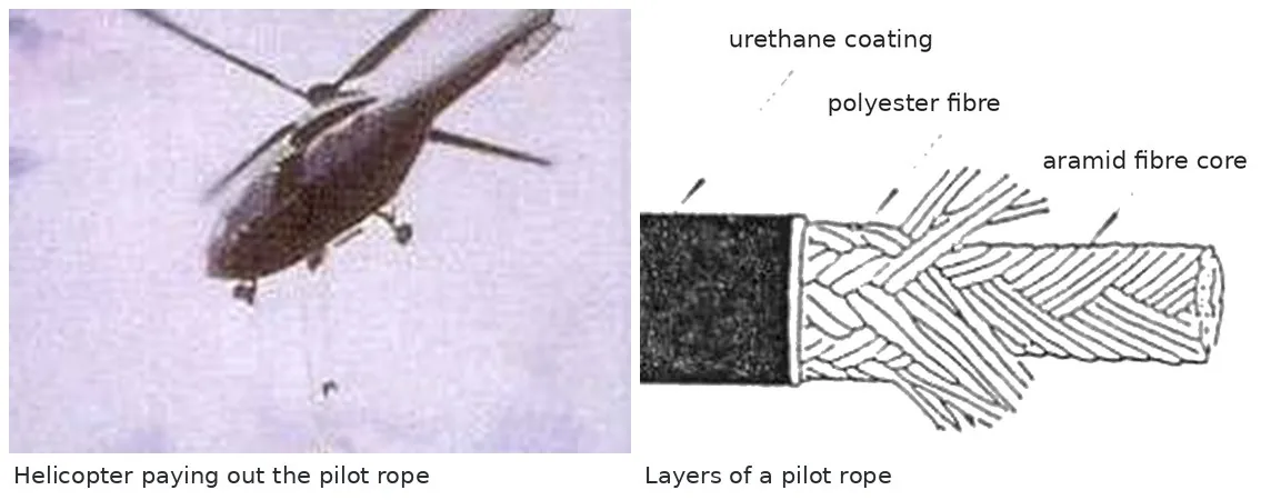
Pilot ropes for long spans are made of light, strong synthetic fibres: an aramid core inside polyester and polyurethane layers, so the rope is strong for its weight and does not absorb water. Where there is no water to tow across, as in deep mountain gorges, other means have been used, including a rocket at the Siduhe Bridge in China.
Two ways to build the main cable
A main cable is not a twisted wire rope. It is tens of thousands of parallel steel wires, about 5 mm in diameter, laid side by side so each takes the same share of the load. Parallel wires give a higher strength and a higher, more reliable elastic modulus than a twisted rope of the same size, but they are much harder to handle, and the whole art of cable erection is laying them parallel, at the right length and the right sag.
| Air spinning (AS) | Prefabricated parallel wire strands (PPWS) | |
|---|---|---|
| What arrives on site | coils of wire, spliced together on site | strands of 61 to 127 wires, made to length in the factory with a socket at each end, delivered on reels |
| How it is laid | a spinning wheel carries a loop of wire from anchorage to anchorage, again and again | a carrier on the hauling rope pulls one whole strand across |
| Strand size | large: hundreds of wires per strand, so few strands | limited by reel weight and transport, so many strands |
| Anchorage | fewer strands, so a smaller anchorage face | more strands and sockets, so a larger anchorage face |
| Fabrication and transport | no strand fabrication, little waste, wire shipped in convenient units | an extra factory step and heavy reels, so higher fabrication and transport cost |
| Time on site | longer | shorter |
| Crew | many skilled workers on the catwalks | fewer |
| Risks | works well around saddles, but a wire can break during spinning; wind affects the free wires | no wire breaks on site, but stiff strands are harder to seat in saddles and splay points |
Neither method wins everywhere. PPWS became the standard method in Japan and on most long spans built since the 1990s because it is fast, needs fewer people and gives a good cable with few crossed wires. Air spinning came back strongly once its wind sensitivity was solved, and it remains the better choice where the anchorage must be small, because each strand can hold far more wires.
Air spinning
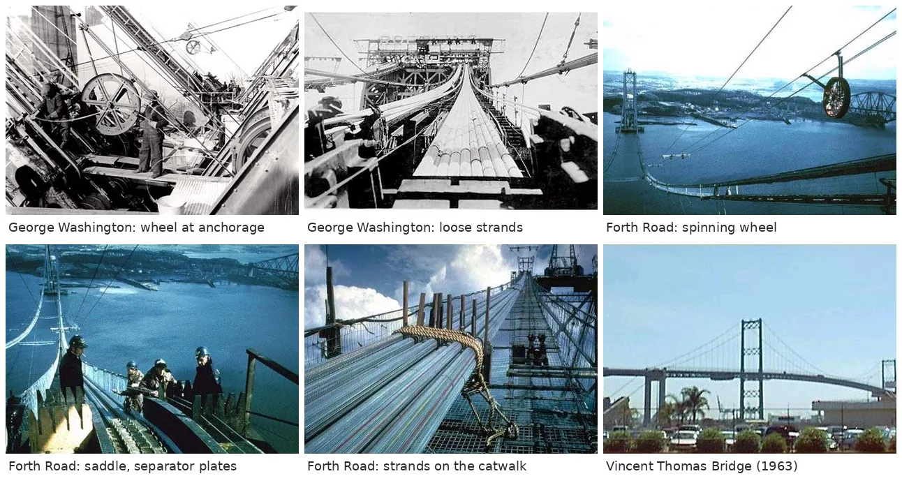
Air spinning was developed by John A. Roebling in the 19th century and used on the Brooklyn Bridge (1883). Wire is fed from reels at one anchorage. A grooved spinning wheel, running on an endless hauling rope above the catwalk like a ski lift, takes a loop of wire across to the far anchorage. One side of the loop, the dead wire, is fixed to a strand shoe at the starting anchorage; the other, the live wire, is fed from the reel at twice the speed of the wheel. At the far end the loop is placed over a strand shoe, and the wheel returns to collect the next loop. When enough wires have been laid to form a strand, typically several hundred, the strand is bound and adjusted, and the next one begins.
Early bridges carried one loop per trip. The George Washington Bridge (1931) moved to two loops per trip, the Golden Gate Bridge (1937) to three, and later bridges to four. Arranging the strands as a hexagon with its points up and down, rather than flat on top, let the Golden Gate cable compact to about 17% voids against about 22% at the George Washington Bridge. On the Forth Road Bridge (1964), stepped saddles with separator plates held each vertical row of strands, so wires could be placed straight into the right groove.
High tension and low tension spinning
In the classic method every wire is spun at its full free-hanging tension and then adjusted one by one, at each span, to the target sag. That gives a precise sag but needs a large crew on the catwalks, and the free-hanging wires move in the wind, so work stops in moderate wind.
The controlled tension (low tension) method fixes this. A counterweight at the starting anchorage holds the wire at a constant tension below the free-hanging tension, and the wire is laid directly into cable formers, slotted frames spaced along the catwalk (about every 10 m), instead of hanging free. Wires are no longer sagged individually; the whole strand is adjusted at the end. The idea was considered in the United States in the early 1960s and first used in full at the Shimotsui-Seto Bridge in Japan (1988), where a tunnel anchorage limited the anchorage width and favoured large spun strands.
| High tension | Low tension (controlled tension) | |
|---|---|---|
| Spinning tension | equal to the free-hanging tension | about 20% to 80% of the free-hanging tension |
| Wire placement | dead wire hung on hooks, live wire on guide rollers, each wire sagged span by span | wires laid into closely spaced cable formers; no individual sag adjustment |
| Sag accuracy | precise, wire by wire | depends on the system: catwalk and strand movement, tension error, wire curvature and temperature all affect length, so preparation and system tuning matter |
| Wire crossings | more, since wires are not held | fewer, since each wire sits in its slot |
| Crew | spinning crew plus sag adjusters at each span | smaller, but each strand is pulled back and lifted once for its final adjustment |
| Wind | sensitive | much less sensitive |
| Equipment | sag adjustment gear at each span | stiff, adjustable cable formers at close spacing; the system must be stable and well controlled |
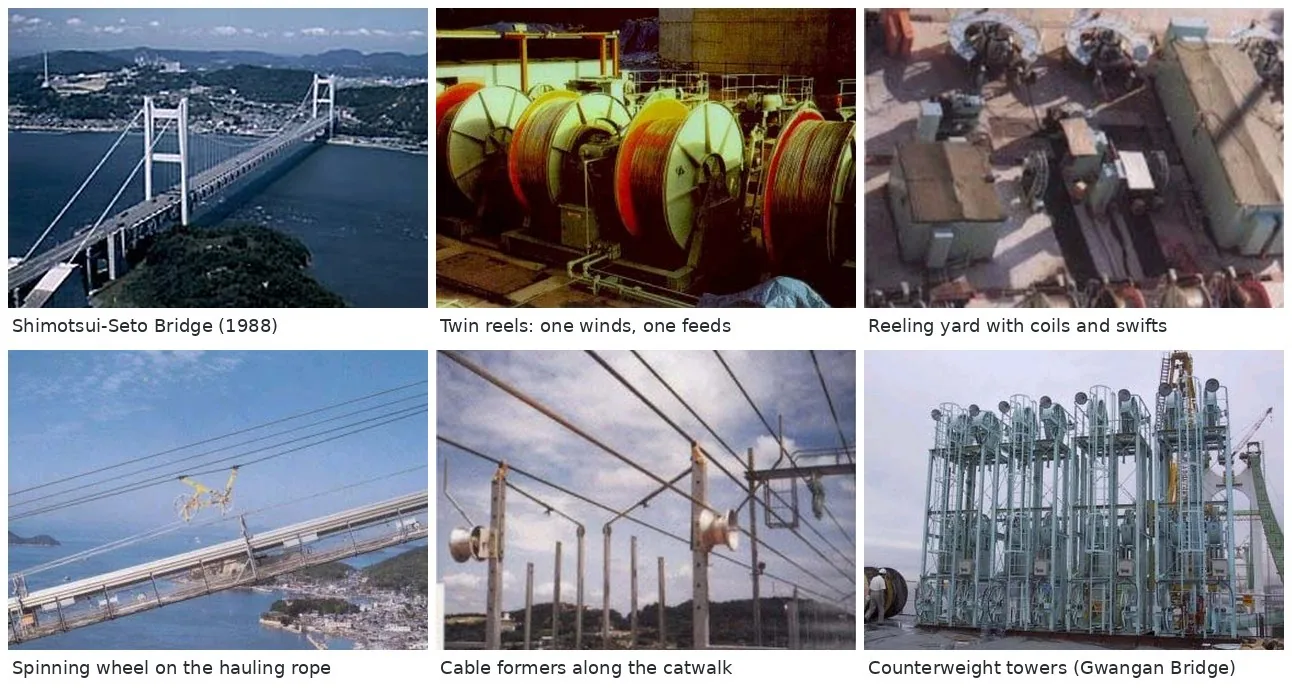
Typical spinning tensions as a share of the free-hanging tension have ranged from about 20% at Shimotsui-Seto to about 50% at Hirado and the Second Bosphorus Bridge, and about 80% at the Great Belt East Bridge.
The Great Belt East Bridge in Denmark (main span 1,624 m, opened 1998) showed what the method can do. Each cable is made of 37 strands of 504 wires. Two tramways per cable each carried two spinning wheels, each wheel pulling four loops per trip, and the counterweight held the wires at about 80% of the free-hanging tension. Spinning ran from July to November 1996 and finished seven weeks ahead of programme, continuing in winds that would have stopped conventional spinning. The output, roughly 2,500 tonnes of wire per cable per month, was about half as much again as the Verrazano-Narrows Bridge. The low tension method then spread through Europe and Asia, including Korea's Gwangan Bridge in Busan (2002); the earlier Yeongjong Grand Bridge used high tension spinning.
Prefabricated parallel wire strands (PPWS)
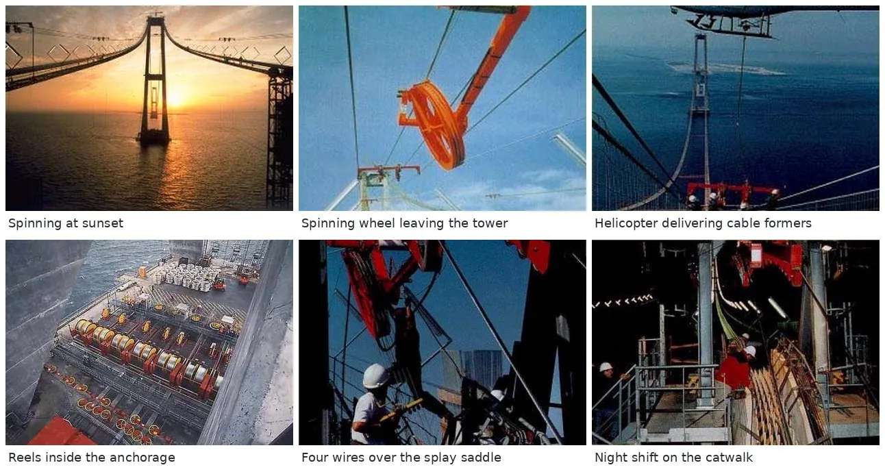
In the PPWS method, also called the PS or PWS method, the parallel wires are bundled in the factory into strands of a hexagonal number of wires (61, 91 or 127), cut to the exact design length and fitted with a socket at each end. The strands are wound on reels, taken to the anchorage, and pulled across one at a time by a carrier on the hauling rope. Because the length is set in the factory, the site work is mostly hauling, sag adjustment of each strand and seating it in the saddles.
The first suspension bridge built this way was the Newport Bridge in Rhode Island (1969). In Japan, the Kamiyoshinokawa Bridge (main span 253 m) was built with one cable by air spinning and the other by PPWS, under the same conditions, and showed that the new method was fully practical. The Kanmon Bridge then moved from 61-wire to 91-wire strands, with shorter site time and better cable quality (void ratio, roundness and fewer crossed wires) than air spinning. The later Honshu Shikoku bridges, Innoshima, Ohnaruto, Kita Bisan-Seto and Ohshima, used 127-wire strands, which reduced both the anchorage width and the programme.
At Akashi Kaikyo each strand was about 4,070 m long and a loaded reel weighed about 100 tonnes, so the unreelers sat on the ground behind the anchorages rather than on top of them, and each catwalk had two hauling lines, four for the bridge, to shorten the programme. Each of its two main cables holds 290 strands of 127 wires, 36,830 wires in all, compacted to a diameter of about 1.12 m.
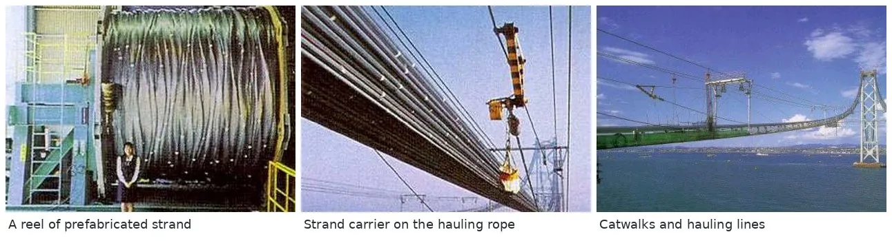
Site equipment for strand hauling
| Item | What it does |
|---|---|
| Unreeler (swift or turntable) | holds the strand reel and pays the strand out |
| Driving winch and tensioner | drives the endless hauling rope and keeps its tension; a hydraulic winch allows high speed, with manual control during the pull |
| Strand carrier | grips the front socket and travels with the hauling rope |
| Tower top, splay and tramway guide rollers | lead the hauling rope over the towers, the splay saddles and the gallows frames at suitable radii |
| Tramway rope and gallows frames | a support rope above the catwalk carrying the frames that hold the hauling rope; later used to install cable bands |
| Strand rollers and cable formers | support the strands along the catwalk; for PPWS the formers are much more widely spaced than for air spinning |
| Storm ropes | tie the catwalks down against wind, fitted at each cross bridge |
| Anchor pit platforms | working platforms where the strand sockets are seated |
| Control room | tension readouts and CCTV covering the whole hauling line |
From strands to a finished cable
When all strands are in place and adjusted, the hexagonal bundle is squeezed round by a compacting machine that travels along the cable, leaving a void ratio of roughly 18% to 20%. Cable bands are clamped on at the hanger points and the hangers are hung from them. The deck is then erected, and only once the cable carries its full dead load is it wrapped, so the wrapping is not stretched by later strain. Wrapping was traditionally galvanised wire over red lead paste. Since the 1990s, starting at Akashi Kaikyo, many cables have been sealed and fed with dry air so the humidity inside stays below the level at which the wires corrode.
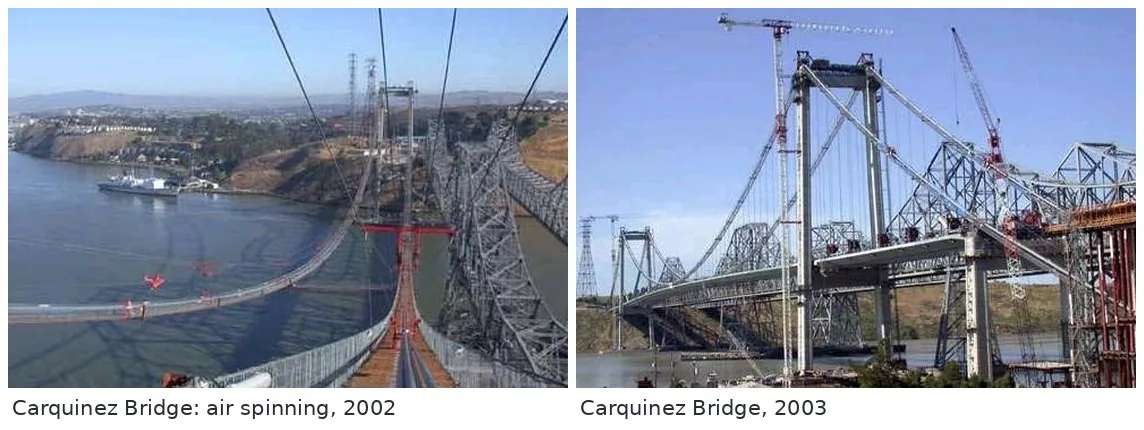
Choosing a method
- Anchorage space is tight (tunnel or rock anchorages, urban sites): air spinning, because a few large strands need less room than many small ones.
- Programme and labour matter most, or several bridges are built at once: PPWS, which is faster on site and needs fewer skilled workers.
- Very long or windy sites: either works if planned for it. Low tension spinning copes with wind; PPWS reduces the time the cable spends exposed.
- Transport limits: PPWS reels for long spans are heavy, so the route to the anchorage and the space for the unreelers must be checked early.
Related on TheBridgeEng
Questions engineers ask
- What is the difference between air spinning and PPWS?
- Air spinning builds the cable on site wire by wire, with a spinning wheel carrying loops of wire between the anchorages. PPWS uses strands of 61 to 127 parallel wires made to length in the factory with sockets on each end, pulled across one strand at a time. PPWS is faster on site; air spinning needs a smaller anchorage.
- How is the first rope taken across a suspension bridge?
- A light pilot rope is towed across on floats, towed hanging free behind a tug, held up by a floating crane, or flown across by helicopter, as at Akashi Kaikyo. Heavier ropes are then pulled across with it to build the catwalks.
- What is low tension (controlled tension) air spinning?
- The wire is held by a counterweight at a constant tension below its free-hanging tension and laid into cable formers along the catwalk, so wires do not need individual sag adjustment and spinning can continue in stronger wind. It was first used in full at Shimotsui-Seto Bridge and later at the Great Belt East Bridge.
- What is a catwalk on a suspension bridge?
- A temporary footbridge hung on its own ropes just below each main cable. Workers and equipment use it to build, compact and wrap the cable, then it is removed.
- Why are suspension bridge cables made of parallel wires?
- Parallel wires share the load evenly and give a higher strength and elastic modulus than a twisted rope of the same size, which keeps the cable smaller and the deck stiffer.
Updated 2026-10-26 · written by a practising bridge engineer